Autocad 3D - Architectural Projects
Creating a Simplified Window in 3D
T. Nicolas MARIE
Please check previous lesson on Creating a hole in Wall for Windows before takling this lesson. We have a wall with a hole 1200x1200 to accomodate a window. In order to create a 3D window, we need to have its sections in CAD, 3D accessoires and its cutting list. We do not have those information and the sake of this lesson we do not need those items as we are going to create a simplified model of a window. The dimensions are mostly arbitrary.
First it is quite handy how views are organized around a top view in Autocad. Below the student will find a top view of the wall 3600x200.
Based on above, the most convenient view to draw the curve profile of the 1200x1200 window is either the FRONT or te BACK view. Curve Profile are built on the XY or working plane. Drawing the curve profile in the FRONT view for example, make it easy to extrude the window to desired thickness. The XY plane of the top view is not adapted for this work. We need the XY plane of the FRONT or BACK view.
There are a number of ways to do this. The simplest method would be to to to the front view first then to the SW isometric view.
This will adapt the UCS of the FRONT view on the SW view. Following this, the student will draw a simplified casement window or 2 set of 600x1200 windows. Use REC or RECTANG to draw a rectangle from any given point to 600,1200. Then O for OFFSET, offset the rectangle 75 mm inward to represent a frame. Enter CO for COPY SELECTION, select the two rectangles, press ENTER to end selection and use grip to duplicate and place the copy side by side.
Use PRESSPULL command and select the bounded spaces in the first window representing the frame and press or pull will do the job. Enter 40 for thickness.
Samething for the second window.
The end result will be as shown below:
Another way would have been to use the EXTRUDE command to extrude the 4 rectangle to a depth of 40 mm and then use SUBSTRACT to have the voids for the glass.
THE GLAZING
For the glazing, create a rectangle and through use of the ENDpoint Oject Snap (make sure ENDpoint is on by entering OS at the command prompt, the minimum object snap is recommended) click the two diagonal ENDpoint within the first window panel.
The student can move the new rectangle away from the window to work on it or another way would be to select the rectangle and right click, choose ISOLATE
With the Rectangle isolated or moved away from the window, use EXTRUDE to give it a depth of 6 mm.
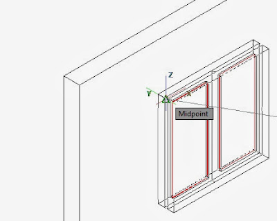
Back to Isolate > Unisolate. Now use M for Move and then CO for COPY SELECTION with MIDpoint Object Snap to move and then copy and place the middleof the glass edge to the center of the frame edge.
Following this, move the the entire window to the hole or bay again using MIDpoint Object Snap.
Remaining job would be to assign materials to the frame, glass and wall. Also adjacent wall and floor construction would greatly enhaced the view to enable so as to see the interior of the room through the window glazing.
Without those additional works, the final drawing would be as follows:
In the next lesson, we will add an adjacent wall and a floor to the project. Then we would have a lesson on Sweep and Revolve with practice the creation of a simplified table and chairs.


Hi Admin, Really Good Post! Keep sharing your post on House Design & House Plans, Architecture 3D Elevations. I like your content and will recommend others to read out your blog House Design
ReplyDelete