Autocad 3D - Architectural Projects
Creating adjacent Wall and Floor in 3D
T. Nicolas MARIE
In this tutorial, we will have a brief look at creating an adjacent wall and floor to the on-going project.
Back to TOP view we draw a rectangle 3600x3000 with first point being endpoint at A. This will draw a rectangular curve profile representing our floor in 2D.
Following creating of the floor curve profile, we are going to draw another rectangle, this time 200x3200 representing the adjacent wall curve profile. The first point of the rectangle will be at B.
The third curve profile will be for the hole in the wall to hold the window. It is a rectangle 200x1200. Following creating of that rectangle, we are going to move it using M for MOVE command with MIDpoint Object Snap represented by a triangle. The base point will be C1 and the insertion point will be C2 which is gained by using the MID Between Two Points Object Snap. The two points is D and E. To get access to the M2P (MID Between 2 Points) Object Snap, SHIFT+Right Click when prompted for the target/destination or insertion poitnt.
Go to the SW Isometric View and we are going to start the extrusions.
First the floor with an extrusion of 150 mm. Enter EXTRUDE or EXT, select rectangle representing floor, ENTER to end selection and with mouse show downward direction and enter 150.
The result will be as follows:
Now EXTRUDE the wall 3000 upward.
We ave already done a hole in a wall in the first lesson. We are going to select the 200x1200 rectangle representing the hole for the window. Right-Click and select Properties or CTRL+1 which will toggle on the Properties Palette. Scroll down to Geometry and click in Elevation and enter 1000. The window is starting at level 1000 above floor level.
Now Extrude 1200 upward.
The result in NE Istometric View in Conceptual visual style.
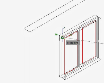
We have already done a window in lesson 2. We are going to reuse it. However please note that the orientation of the window does not match the orientation of the wall. We should rotate it or re-align it. In this lesson, we will realign the window and position it within the hole with the command 3DALIGN. This command require that we select the Window, press Enter to end selection. Then it will ask the student 3 source point on the window and 3 destination point in the hole. We will need the MIDpoint Object Snap in selecting those 6 points. Enter OS previous to 3D align and make sure that MIDpoint is selected.
In the pictue below, the student will find the 3 source points on the window and the 3 destination points in the hole in the wall.
The next screen show what happen after the third source point has been selected. The window now come with the crosshair.
This is the end result following selecting the 3 destination points.
Now, we will need to draw the plinth level which is 450 mm deep. Continuing in the NE Isometric View, we are going to assure that the XY axis match the top elevation. Go to top view and back to NE Isometric View. Now use Polyline (alias: PL) and draw the curve profile using ENDpoint Object Snap grips. Making another colour current by entering COL for COLOR previous to creating the polyline.
Now extrude downward 450 mm.
Now we will joint the upper wall and the lower wall to form one single unit. Enter UNI for UNION and select all wall and press ENTER.
The End Result should look like this. Next time we will add a table and some chair and introducing SWEEP and REVOLVE command. Then we will have a separate lesson on Rendering.


