Facebook Page

Wednesday, 25 September 2013

Autocad 3D - Architectural Projects - Creating adjacent wall and floor in 3D

Autocad 3D - Architectural Projects  
Creating adjacent Wall and Floor in 3D
T. Nicolas MARIE

In this tutorial, we will have a brief look at creating an adjacent wall and floor to the on-going project. 

Back to TOP view we draw a rectangle 3600x3000 with first point being endpoint at A. This will draw a rectangular curve profile representing our floor in 2D.


 Following creating of the floor curve profile, we are going to draw another rectangle, this time 200x3200 representing the adjacent wall curve profile.  The first point of the rectangle will be at B.


 The third curve profile will be for the hole in the wall to hold the window.  It is a rectangle 200x1200.  Following creating of that rectangle, we are going to move it using M for MOVE command with MIDpoint Object Snap represented by a triangle.  The base point will be C1 and the insertion point will be C2 which is gained by using the MID Between Two Points Object Snap.  The two points is D and E. To get access to the M2P (MID Between 2 Points) Object Snap, SHIFT+Right Click when prompted for the target/destination or insertion poitnt.


 Go to the SW Isometric View and we are going to start the extrusions.


 First the floor with an extrusion of 150 mm. Enter EXTRUDE or EXT, select rectangle representing floor, ENTER to end selection and with mouse show downward direction and enter 150.  


The result will be as follows:  


 Now EXTRUDE the wall 3000 upward.


 We ave already done a hole in a wall in the first lesson.  We are going to select the 200x1200 rectangle representing the hole for the window. Right-Click and select Properties or CTRL+1 which will toggle on the Properties Palette. Scroll down to Geometry and click in Elevation and enter 1000. The window is starting at level 1000 above floor level.


 Now Extrude 1200 upward.


 The result in NE Istometric View in Conceptual visual style.


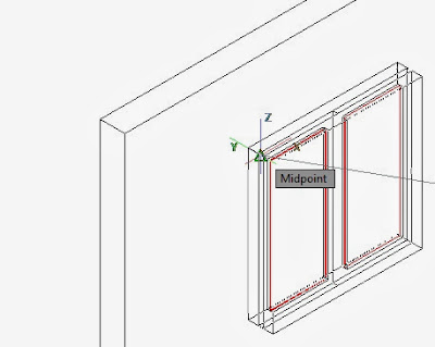
We have already done a window in lesson 2.  We are going to reuse it.  However please note that the orientation of the window does not match the orientation of the wall.  We should rotate it or re-align it.  In this lesson, we will realign the window and position it within the hole with the command 3DALIGN.  This command require that we select the Window, press Enter to end selection.  Then it will ask the student 3 source point on the window and 3 destination point in the hole.  We will need the MIDpoint Object Snap in selecting those 6 points.  Enter OS previous to 3D align and make sure that MIDpoint is selected. 


 In the pictue below, the student will find the 3 source points on the window and the 3 destination points in the hole in the wall.


 The next screen show what happen after the third source point has been selected.  The window now come with the crosshair.


This is the end result following selecting the 3 destination points.


 Now, we will need to draw the plinth level which is 450 mm deep.  Continuing in the NE Isometric View, we are going to assure that the XY axis match the top elevation.  Go to top view and back to NE Isometric View. Now use Polyline (alias: PL) and draw the curve profile using ENDpoint Object Snap grips.  Making another colour current by entering COL for COLOR previous to creating the polyline.


 Now extrude downward 450 mm.


 Now we will joint the upper wall and the lower wall to form one single unit. Enter UNI for UNION and select all wall and press ENTER.


 The End Result should look like this. Next time we will add a table and some chair and introducing SWEEP and REVOLVE command.  Then we will have a separate lesson on Rendering. 

Monday, 23 September 2013

AutoCAD 3D - Creating a Simplified Window in 3D

Autocad 3D - Architectural Projects  
Creating a Simplified Window in 3D
T. Nicolas MARIE
Please check previous lesson on Creating a hole in Wall for Windows before takling this lesson.  We have a wall with a hole 1200x1200 to accomodate a window.  In order to create a 3D window, we need to have its sections in CAD, 3D accessoires and its cutting list.  We do not have those information and the sake of this lesson we do not need those items as we are going to create a simplified model of a window.  The dimensions are mostly arbitrary.

First it is quite handy how views are organized around a top view in Autocad.  Below the student will find a top view of the wall 3600x200. 


Based on above, the most convenient view to draw the curve profile of the 1200x1200 window is either the FRONT or te BACK view.  Curve Profile are built on the XY or working plane.  Drawing the curve profile in the FRONT view for example, make it easy to extrude the window to desired thickness. The XY plane of the top view is not adapted for this work.  We need the XY plane of the FRONT or BACK view.

There are a number of ways to do this.  The simplest method would be to to to the front view first  then to the SW isometric view.  


 This will adapt the UCS of the FRONT view on the SW view. Following this, the student will draw a simplified casement window or 2 set of 600x1200 windows.  Use REC or RECTANG to draw a rectangle from any given point to 600,1200.  Then O for OFFSET, offset the rectangle 75 mm inward to represent a frame. Enter CO for COPY SELECTION, select the two rectangles, press ENTER to end selection and use grip to duplicate and place the copy side by side.


Use PRESSPULL command and select the bounded spaces in the first window representing the frame and press or pull will do the job.  Enter 40 for thickness.


 Samething for the second window.


 The end result will be as shown below:


Another way would have been to use the EXTRUDE command to extrude the 4 rectangle to a depth of 40 mm and then use SUBSTRACT to have the voids for the glass.

THE GLAZING

For the glazing, create a rectangle and through use of the ENDpoint Oject Snap (make sure ENDpoint is on by entering OS at the command prompt, the minimum object snap is recommended) click the two diagonal ENDpoint within the first window panel.


The student can move the new rectangle  away from the window to work on  it or another way would be to select the rectangle and right click, choose ISOLATE


 With the Rectangle isolated or moved away from the window, use EXTRUDE to give it a depth of 6 mm.


Back to Isolate > Unisolate.  Now use M for Move and then CO for COPY SELECTION with MIDpoint Object Snap to move and then copy and place the middleof the glass edge to the center of the frame edge.


Following this, move the the entire window to the hole or bay again using MIDpoint Object Snap.


Remaining job would be to assign materials to the frame, glass and wall. Also adjacent wall and floor construction would greatly enhaced the view to enable so as to see the interior of the room through the window glazing. 

Without those additional works, the final drawing would be as follows:  


In the next lesson, we will add an adjacent wall and a floor to the project.  Then we would have a lesson on Sweep and Revolve with practice the creation of a simplified table and chairs.


Sunday, 22 September 2013

Autocad 3D - Architectural Projects  
Creating Hole in Wall for Windows
T. Nicolas MARIE

In this tutorial, we are going to create a rectangle polyline 3600x200 in XY plane of Top view and we will extrude it 3000 along the Z-axis to give it height.  It is interesting to know that this is not the sole way of creating a wall in Autocad.  The student can also use BOX or PRESSPULL. Following the creation of our 3D wall, we will then make a hole of 1200x1200 in the wall representig te location of our window.

The extrude command works with closed polylines to create solid or surface.  The default result is a solid.  If we use lines, arcs or opened polylines, extrude results in surface.  Polar Tracking, Midpoint Snap (Enter OS and select MIDpoint) and Dynamic Input should be on.  The DWG file should be based on the ACADIso.dwt template as we are going to work in metric where 3600x200 are mm.

Create a rectangle 3600 by 200.


Change the view to SW to move from 2D to 3D.


 Use commad alias EXT for EXTRUDE. Select Object and Press Enter to End Selection, move mouse upward to show direction of Extrusion (here positve value of Z) and give height 3000.


The end result is a solid representing a 3600x3000 200-mm wide wall.


Now back to TOP view to create the curve profile for the window. Use REC or RECTANG to create rectangle 1200x200.  The dimension can be checked by clicking this rectangle and hover the crosshair over the grip for 1-2 seconds.


Now position window by insing MIDpoint Object Snap and Move command (alias: M). Move command require the selection of the 1200x200 rectangle, a basepoint and an insertion point.

Following positioning process, select the 1200x200 rectangle and press CTRL+1 or right click same object and choose Properties.  Change the elevation to 1000.

The end result will look like this:


It should be noted that all objects drawn on the top view are drawn to elevation 0 that is the value of Z is 0.  In this case, we have selected the 1200x200 rectangle and set if to a different value, move it up along Z by 1000.

Now use EXT for EXTRUDE to extrude the object 1200 upward.


Use SU for SUBSTRACT and first select the wall and press ENTER to end selection.  The first selection is the object that will remain after the substracting.  It is the object from which materials will be removed.


Then select materials to be removed and press ENTER to complete the sustracting process.


Note that SUBSTRACT, UNION and INTERSECT are also known as BOOLEAN operators. The End result using a different viewstyle (Say Conceptual):


Monday, 8 July 2013

Building and Land Use Permit in Mauritius


An Introduction
By T. Nicolas MARIE


Prior to receiving a Building and Land Use Permit (BLP) from the Municipalities and District Councils in Mauritius, the applicant and the draughtsman should ascertain 3 main things namely:

1. Title Deed ("Contrat") is available and contains name of applicant (or owner of plot of land). The last page of the Title Deed usually contain the TV (Transcript Volume) Number.


2. Required Documents with necessary approvals (Clearance from CEB, CWA and Waste Water Management Authority, Letter of Consent duly signed by neighbor(s) where setback is less than 900 mm, Contour plan if basement is proposed...) are submitted along with 3 sets of plans along with BLP form duly signed by both applicant and draughtsman where applicable.

For CEB clearance, needed plans are 2 copies of location and site plans and elevations. Clearance will cost Rs. 375 /- payable when clearance is obtained.

For CWA clearance, needed plans are a single copy of location and site plans, layouts, elevations and sections.   Clearance will cost Rs. 345 /- payable when application is made.  An exception is the CWA at Mutual Aid Building, Port Louis where 2 copies are needed and clearance is received same day on Wednesdays.

Application for CEB and CWA Clearances should be made to the office nearest to the site.  Those clearances are required for all new projects.  For extension or addition of floors, only CEB Clearance is needed. 

WWMA Clearance will cost approx. Rs. 800 /- and application is made only at Port Louis.  This clearance is mostly sought where there is connection to main sewer (in town only) and apartments.

Needed Documents as appeared in older BLP application


3.  Site and subsequently all layout plans must been done respecting limits shown on title deeds and as per the Building and Land Use Permit guideline.  The site plan should be detailed with name of neighbours, street name and width, dimension of sides and rear setbacks, road reserves, parking where applicable and external sewerage system (septic tank, absorption pit or leech field, manholes, grease trap and sewerage lines) clearly depicted and dimensions between to building corners and septic tank and between same and boundary lines.  Recently there has been an emphasis on Rain Water Pipe, Catchpits and Soakaway that need to be shown on site plan.  Required Plans are:

a. Location Plan
b. Site Plan
c. Layout Plan
d. Elevations (Generally 4 elevations)
e. Sections (Generally 2 sections: Longitudinal and Cross Sections)
f. Foundation Layout
g. Surface Bed, Walls, Strip Footing and Pad Footing Details
h. Column Details
i. Beams Details
j. Slabs Layout
k. Staircase Details
l. Septic Tank and other external sewerage components details

Note that a to e plans are known as architectural plans and f to l plans as structural plans.

THE BUILDING AND LAND USE PERMIT FORM (BLP1)

The BLP1 form for Residential House consist of 8 pages including cover page and divided into 3 parts.  The first part (pages 2 ad 3) is to be filled by the applicant/client while the remaining Part B and C to be filled by the service provider.  Part A is straight forward starting with the applicant contact details, details concerning the land on which the building will sit i.e Location, Extent, TV No.  Those information is readily available in the Title Deed. 

Site Information


There is also a section within that part inquiring whether the applicant is owner of the land. Should the answer be NO, the ID of the Owner should be photocopied and submitted along with the remaining document. The owner of the site must also provide a written authorisation letter to the applicant.

Is the Applicant Owner of the Site?


As stated Part B and C concerned the Draughtman.  However the applicant should know the following guidelines with respect to his/her building project:

1. Engineer's approval is needed for the following cases: 
a. Effective Span exceed 5m.  Effective Span is the distance between the center of supports (here Reinforced Concrete Columns).
b. Ground + 2 construction 
c. Cantilever Beams/Slab exceeds 1.2m
d. Natural Slope of Land greater than 1:20

2. For floor area exceeding 150 m2 or 1614 sq. ft. (See BLP Guide 2013), the plans should be approved and signed by a professional architect.  

3.  The building should be surrounded at sides and rear by a minimum setback of 900 mm. Even more in case of a Ground + 2 where building height exceeds 7.5m.  Hence should the applicant plan on having a second floor at a later stage, he/she should provide for a 2m setback right from the start. 

The Reserve is specified in the title deed (if not, see the land surveyor report).  It is to be noted that Boundary wall should not be erected within the reserve.

 
Set Backs


4.  Another critical issue is the septic tank and absorption pit.  There is to be a minimum distance of 2m between the septic tank and the building and 2m from the septic tank to the boundary line.  People in process of buying land should make sure they have enough space for septic tank and absorption pit, even more for road A and B or where leech field is specified especially in Coastal Regions.


Septic Tank


Part C of the BLP is the schedule of payment. The greater the floor areas, even greater the cost as the rate increased for area greater than 250 m2.   For example, a floor area of 200 m2 cost Rs. 2000 (200 x Rs. 10), a floor of 400 m2 is twice the area but the price is Rs. 8000 (that is 400 x Rs. 20, hence 4 times) and a floor area of 600 is thrice the initial area but the price is Rs. 30,000 (that is 600 x Rs. 50, hence 15 times).


Should you have any further questions or any issues where I can help, please do not hesitate to contact me.